


压电双材料界面裂纹的强度因子分析
[孟广伟 , 李荣佳, 王欣, 周立明, 顾帅]
, 李荣佳, 王欣, 周立明, 顾帅]
|
|


作者简介:孟广伟(1959-),男,教授,博士研究生. 研究方向:工程结构的断裂与疲劳. E-mail:mgw@jlu.edu.cn
为满足实际工程中对求解压电双材料界面裂纹强度因子方法通用性和有效性的要求,基于压电界面断裂力学推导了压电双材料平面及反平面界面裂纹强度因子显示外推公式,通过力电耦合有限元模拟了裂纹尖端附近的位移场和电场,将裂纹尖端后面的裂纹张开位移和电势跃变代入强度因子显示外推公式,求解压电双材料的界面裂纹强度因子。以含中心裂纹压电双材料板为例,对不同载荷、单元数和加密形式下的强度因子进行了讨论,并与解析解作了对比。数值算例结果表明,本文方法具有计算简单、精度高等优点。
In order to meet the requirement of commonality and effectiveness in solving the intensity factors of piezoelectric bimaterials with interface crack in practical engineering, based on piezoelectric interface facture mechanics, an explicit extrapolating formula of intensity factors for in-plane and anti-plane interface crack was derived. The interface crack-tip displacement field and electric filed of the piezoelectric bimaterials were simulated using the electromechanical coupling computation methods. Substituting the crack displacement and the electric potential jump at the back of the crack tip into the explicit extrapolating formula, the intensity factors of piezoelectric bimaterials with interface crack were solved. Considering a center interface crack in double piezoelectric plates, the intensity factors under different loadings, different numbers of elements, and different mesh refinement methods were discussed and compared with the analytical solution. Results of numerical examples show that the proposed method has the advantages of simple calculation and high accuracy.
压电材料具有良好的力电耦合效应, 在智能材料和智能结构中发挥着重要的作用, 尤其在传感技术、驱动技术、超声技术和电子声学技术领域占有重要的地位。在实际工程中, 压电元件常以层状结构出现来提升其传感和驱动效果。压电材料所固有的脆性, 使其在制备及服役过程中易产生界面缺陷, 界面裂纹往往是该结构破坏的主要形式。近些年, 压电双材料界面裂纹的分析取得了一些成果。Govorukha等[1]对压电材料的界面裂纹的研究进展进行了综述。Ou等[2, 3, 4]提出了压电双材料在力电耦合作用下的界面裂纹奇异理论。Nishioka等[5, 6, 7]给出了含界面裂纹压电双材料的J积分。Suo等[8]推导了异相压电材料界面裂纹尖端处的裂纹张开位移和电势跃变与强度因子的隐式表达式。研究压电双材料的界面裂纹问题具有重要学术价值。
随着计算机硬件和软件的发展, 数值模拟方法成为求解压电双材料的断裂力学问题不可或缺的手段[9]。Lei等[10]基于边界元法研究了各向异性压电双材料在力电耦合冲击载荷作用下的动态强度因子。Ma等[11]基于扩展有限元法计算了含裂纹压电双材料的J积分。Fang等[12]采用无网格法对压电界面裂纹尖端处的应力场和电场进行了模拟。Zhao等[13]基于Green函数和位移阶跃性对界面压电材料进行了研究。Gherrous等[14]推导了反平面载荷作用下无限大板和半无限大板J积分公式。Sladek等[15]基于无网格法对力载作用下的压电界面裂纹问题进行了分析。Loboda等[16]研究了压电双材料接触区域界面裂纹问题。Feng等[17]分析了压电双材料多界面裂纹问题。Choi等[18]对压电双材料三共线反平面裂纹进行了研究。目前, 新型数值计算方法缺乏通用性[19]。求解断裂参数的J积分求解较为复杂, 虚拟裂纹闭合法[20]计算精度相对较低, 工程实际中需求简单有效的求解压电双材料界面裂纹强度因子方法。
本文基于广义直接位移法求解裂纹尖端附近的位移场和电场。推导了裂尖强度因子显示外推公式, 并从力电耦合有限元计算结果中提取相关数据代入压电双材料界面裂纹的位移外推法中, 求解了压电双材料界面裂纹的强度因子。
考虑广义平面压电双材料问题如图1所示,
 | 图1 一个半无限压电双材料的界面裂纹Fig.1 An interface crack in a semi-infinite piezoelectric bimaterials |
广义位移u(位移ui和电势φ )和广义应力σ (应力σ i2和合力D2), 其一般解可用四维Stroh形式[15]:
u=2Re
式中:
u=
f(z)为四阶复合势函数, 如下:
f(z)=
zα =x1+pα x2(6)
式中:pα 为式(7)特征方程中虚部大于零的特征值, 对应于pα 的特征向量为aα
式中:
Q=
R=
T=
式中:cijkl为弹性常数; ekij为压电常数; gik为介电常数。
矩阵A和B由式(7)的特征向量组成:
A=
B=
对于不可渗透双压电材料界面时, Hermitian矩阵Y和H为:
Y=iAB-1(14)
H=Y(1)+
式中:上标(1)和(2)代表材料1和材料2。
裂纹尖端场的奇异性归结为以下特征值问题:
ω =e2π γ Hω (16)
式中:ω 为Hermitian矩阵特征值问题所对应的特征的量。
把矩阵H拆分成一个实部D和一个虚部W, 如下:
H=D+iW(17)
由式(16)得:
‖ D-1W+iβ I‖ =β 4+2bβ 2+c=0(18)
式中:
γ =-arctanβ (19)
b=tr
c=‖ D-1W‖ (21)
式中:β 为式(18)的根; γ 对应的值± ε 、± iκ 互为共轭对; “ tr” 为矩阵的迹。
由于W为偶次的反对称矩阵≥ 0, 又由于< 0, 所以c≤ 0, 因此γ ≥ 0。振荡参数ε 和κ 为:
ε =cot
κ =cot
该问题广义位移差δ i(i=1, 2, 3, 4)与强度因子Ki(i=1, 2, 3, 4)的关系为:
式中:K1为Ⅰ 型裂纹的应力强度因子; K2为Ⅱ 型裂纹的应力强度因子; K3为Ⅲ 型裂纹的应力强度因子; K4为电位移强度因子。
S=ω diag·
式中:r为距裂尖距离。
对式(24)中的平面和反平面裂纹问题进行分析。对于平面界面裂纹问题, 距裂纹尖端r处的张开位移和电势跃变为:
式中:当b≤ 0时, ζ 1=riε
T1=2H
T2=2HE
T3=2HE2
式中:I为单位矩阵; E=WD-1。
整理式(26), 得到裂纹尖端强度因子显示外推公式:
式中:
M=
对于反平面界面裂纹问题, 位移场和电势场仍然保持平方根奇异性, 有
Y=iAB-1=
式中:c44、e15和g11分别为弹性矩阵系数、压电矩阵系数和介电矩阵系数。
式(15)可改写为:
H=Y(1)+
H11=
H12=H21=
H22=
式中:(i)为材料i的材料参数。
整理式(24), 得到反平面裂纹裂尖强度因子显示外推公式:
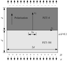
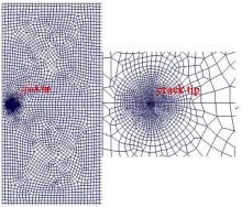
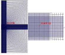
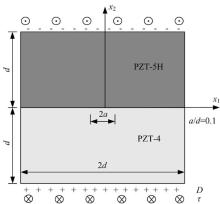
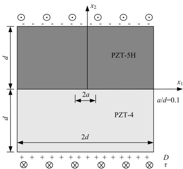
由PZT-4和PZT-5H组成的中心裂纹为2a的双压电材料, 材料参数如表1所示。受σ =1.0 MPa的拉应力和D=0.001 C/m2的电位移, 极化方向为x2方向, 几何尺寸为2d=40 mm× 40 mm, 中心裂纹长度2a=4 mm, 如图2所示。由于载荷和结构的对称性, 取模型的一半计算, ABAQUS采用CPS8E单元, 裂尖处采用图3~图5所示的开裂前3种单元划分模式(Ⅰ :圆形加密、Ⅱ :均匀加密和Ⅲ :矩形加密)。
表2给出了不同载荷及网格加密时距裂纹尖端0.02a处的裂纹张开位移和电势跃变, 由显示外推公式(30)得到其强度因子。表3给出了3种网格加密形式时力场单独作用下强度因子计算结果与解析解, 并给出了误差。表4给出了3种网格加密形式时电场单独作用下强度因子计算结果与解析解。表5给出了3种网格加密形式时力电耦合作用下强度因子计算结果与解析解, 并给出了误差。可见, 3种计算模型下均得到了精度较高的强度因子, 与解析解比较, 最大误差仅为3.9%, 采用圆形加密方式下的强度因子计算精度最高。
| 表1 材料常数 Table 1 Material constants |
 | 图2 双压电材料中心界面裂纹Fig.2 Interfacial center crack in piezoelectric bimaterials |
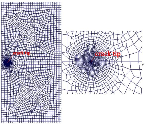 | 图3 裂尖圆形加密(Elements:4026)Fig.3 Round refinement at crack tip (Elements:4026) |
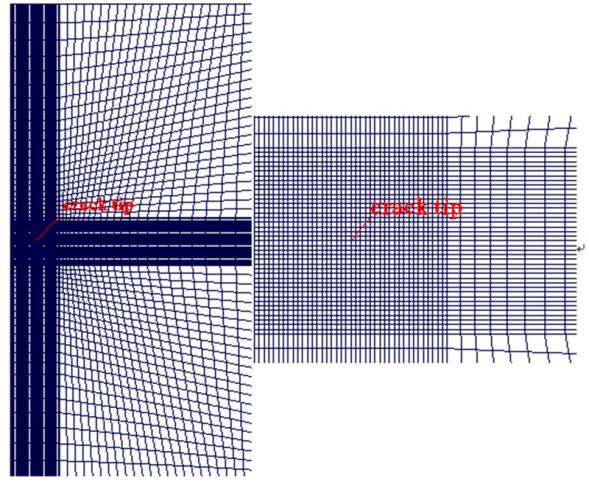 | 图4 裂尖均匀加密(Elements:5418)Fig.4 Uniform refinement at crack tip (Elements:5418) |
 | 图5 裂尖矩形加密(Elements:6987)Fig.5 Rectangular refinement at crack tip (Elements:6987) |
| 表2 不同载荷及网格加密时裂纹张开位移与电势跃变 Table 2 Crack opening displacement and electric potential jump by different loadings and mesh refinement methods |
| 表3 在力载荷作用时不同网格加密下强度因子 Table 3 Intensity factors by different mesh refinement methods under mechanical loading |
| 表4 在电载荷作用时不同网格加密下强度因子 Table 4 Intensity factors by different mesh refinement methods under electric loading |
| 表5 在力电载荷作用时不同网格加密下强度因子 Table 5 Intensity factors by different mesh refinement methods under electromechanical loading |
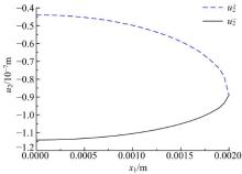
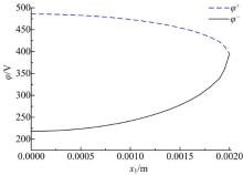
图6和图7分别给出了电载荷作用时圆形加密方式下裂纹线上节点位移值和电势值, 提取裂纹尖端后面0.02a~0.6a范围附近裂纹张开位移及电势跃变可以得到稳定收敛的强度因子。对于裂纹尖端网格加密方式, 在CPU:Inter(R) Core(TM) i5-3470 3.20 GHz, RAM:8GB情况下, 力电载荷作用时, 圆形加密耗时1.7 s, 均匀加密耗时2.2 s, 矩形加密耗时2.9 s。裂尖采用圆形加密方式计算强度因子具有方法便捷、精度高、耗时少等优点。
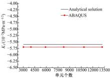
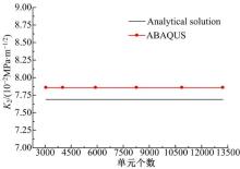
图8~图10分别给出了力电载荷作用下, 加密区域内单元类型和数量不变, 采用圆形网格加密时单元个数(3058、4026、5907、8256、10866和13217)与强度因子的关系图。可见, 强度因子受加密区域以外的单元影响比较小, 主要受加密区域内单元的加密形式的影响。
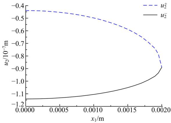 | 图6 电载荷作用时裂纹张开位移Fig.6 Crack opening displacement under electric loading |
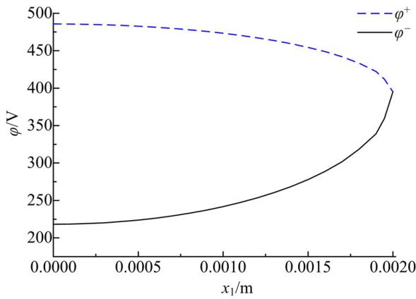 | 图7 电载荷作用时电势跃变Fig.7 Electric potential jump under electric loading |
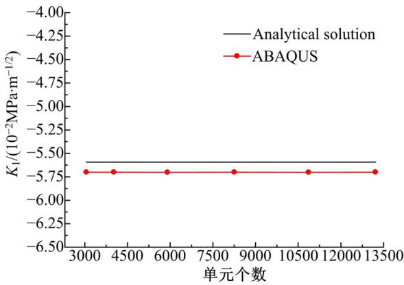 | 图8 强度因子K1与单元个数的关系Fig.8 Relationship between intensity factor K1 and number of elements |
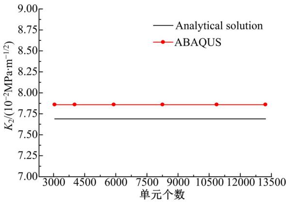 | 图9 强度因子K2与单元个数的关系Fig.9 Relationship between intensity factor K2 and number of elements |
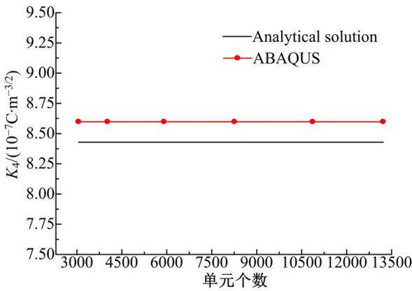 | 图10 强度因子K4与单元个数的关系Fig.10 Relationship between intensity factor K4 and number of elements |
如图11所示, 无限大压电双材料中有一中心长为2a=10 mm的穿透裂纹, 材料参数由PZT-5H和PZT-4组成。在边界受远场载荷τ =5.94 MPa和D=0.003 C/m2, x1轴沿界面方向, x3轴为压电材料的极化方向。
 | 图11 压电双材料反平面界面裂纹Fig.11 Anti-plane interface crack in piezoelectric bimaterials |
表6给出了力电载荷作用时反平面界面强度因子计算结果与解析解, 并给出了误差。与解析解比较, 最大误差仅4.8%。可见, 本文方法具有方法便捷、精度高等优点。
| 表6 在力电载荷作用时反平面界面强度因子 Table 6 Anti-plane interface intensity factors under electromechanical loading |
(1)基于强度因子显示外推公式, 通过提取相应裂纹张开位移和电势跃变计算强度因子具有方法便捷、精度高等优点。
(2)当裂尖处采用圆形区域加密时, 求解精度最高, 效率最高。
(3)强度因子受加密区域以外的单元影响比较小, 主要受加密区域内单元加密形式的影响。
The authors have declared that no competing interests exist.
| [1] |
|
| [2] |
|
| [3] |
|
| [4] |
|
| [5] |
|
| [6] |
|
| [7] |
|
| [8] |
|
| [9] |
|
| [10] |
|
| [11] |
|
| [12] |
|
| [13] |
|
| [14] |
|
| [15] |
|
| [16] |
|
| [17] |
|
| [18] |
|
| [19] |
|
| [20] |
|